
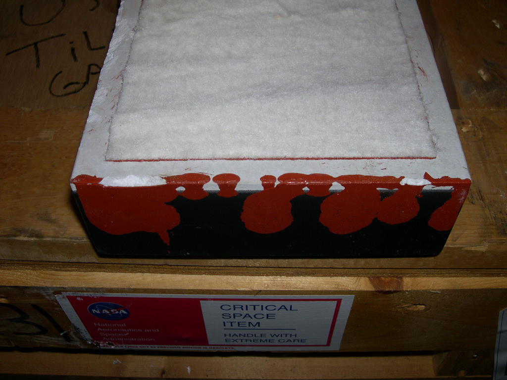
Ok so picture 1, you see a tile. The soft looking stuff is called "Sip". You see the red stuff that has smeared on the tile side wall? Well that is called RTV.
In the next picture, that's the Gap Filler. Now not every single tile on the orbiter needs a gap filler. It's just that sometimes, there are gaps in between the tile and in order to prevent any type of air/heat flow to enter through the cavity, a gap filler is installed.
So this is it upclose. Going back to the tile picture, the side with the soft looking side is what is attached to the surface of the orbiter. So the other side of the tile is black and has a part number sprayed on it. This is what you see on the whole belly side of the orbiter.
Once the tiles are installed is when the gap fillers are installed. So right now, the installation of the gap fillers is what is trying to be perfected. The red RTV is applied to the gap filler and the issue right now is that when it installed, the RTV smears or droops down against the tile sidewall, which creates less bonding closer to the surface.
But this is why we have great team working on this. They are testing new methods, coming up with the reasons certains ones have failed, and we are doing alot of failure analysis.
Till next time everyone.. and I promise it won't be like 2 weeks later. Take care.
P.S By the way.. the rope loops that you see in the gap filler pictures are not part of the installation. They are doing pull tests in that picture to see how many pounds it can withstand until it fails.


